Atmospheric Gas Water Heater Maintenance
MAINTENANCE FOR YOUR ATMOSPHERIC GAS WATER HEATER
KEEP YOUR UNIT RUNNING AT OPTIMAL EFFICIENTY
Routine maintenance will help your water heater last longer and work better. If you can’t perform these routine maintenance tasks yourself, contact a qualified person.
The following information is provided in the Installation Instructions and Use & Care Guide from AO Smith for the Residential Gas Water Heater.
Please always refer to the installation guide before performing any routine maintenance checks. If the information in these instructions is not followed exactly, a fire or explosion may result causing property damage, personal injury or death.
Draining and Flushing the Water Heater
Tap water contains minerals that can form sediment in the bottom of the tank. The amount of sediment formed depends on the hardness of your tap water, the temperature settings, and other variables. We recommend draining and flushing the water heater after the first six months of operation to determine the amount of sediment build up. If there is little sediment, drain and flush the tank annually. If there is a lot of sediment, drain and flush the tank more often. Draining sediment extends the life of the water heater.
To Drain and Flush the Tank
Turn the gas control knob on the gas control valve to the OFF position.

1. Turn the manual gas valve for the water heater’s supply line OFF.
2. Open a hot water faucet and let the hot water run until it is cool (This may take 10 minutes or longer).
WARNING! Be sure the water runs cool before draining the tank to reduce the risk of scalding.
3. Open a hot water faucet and let the hot water run until it is cool (This may take 10 minutes or longer)

4. Connect a garden hose to the drain valve and place the other end of the hose in a drain, outside, or in buckets. Note that sediment in the bottom of the tank may clog the valve and prevent it from draining. If you can’t get the tank to drain, contact a qualified person.
5. Turn the cold water supply valve OFF.
6. Open the drain valve on the water heater.

7. Also open a hot water faucet to help the water in the tank drain faster.
8. Remove and inspect the anode rod and replace if depleted. The anode rod requires a 1-1/16” socket.

Anode Rod. The anode rod is a sacrificial metal rod that helps avoid corrosion and premature failure (leaks) in the tank. The anode rod is a consumable item. Inspect the anode rod after the first six months of operation when you drain and flush the tank. Replace the anode rod if it is substantially worn out or depleted. Thereafter, inspect the anode rod annually or more frequently if needed. If you use a water softener, your anode rod will deplete faster than normal. Inspect the anode rod more frequently, replacing the anode rod if it is depleted. Obtain a new anode rod from your local plumbing supplier or have a qualified person replace it. (Anode rods are a consumable item and are not covered under warranty).
9. If a large amount of sediment was present when the tank was drained, flush the tank by opening the cold water supply valve and letting the water run until no more sediment drains from the tank. Close the drain valve when you are done.
10. Refill the tank by opening the cold water supply valve. Make sure a hot water faucet is open and the drain valve is closed. Allow a hot water faucet to run full for at least three minutes to make sure the tank has all the air removed and is completely full of water. Once you are certain the tank is completely full of water, close the hot water faucet.
11. Relight the pilot using the instructions on page 23 and adjust the gas control knob to the desired temperature. It may take an hour or more for the tank of cold water to heat up.
Visual Inspection
On an annual basis, visually inspect the venting and air supply system, piping systems, main burner, pilot burner, and the air filter.
Check the water heater for the following:
1. Obstructions, damage, or deterioration in the venting system. Make sure the ventilation and combustion air supplies are not obstructed. Check the air filter for dust or other debris and clean if needed.
2. Build up of soot and carbon on the main burner and pilot burner. The burner may be cleaned with soap and hot water.
3. Inspect the burner flames through the viewport and compare them to the drawing below. A properly operating burner should produce a soft blue flame. Blue tips with yellow inner cones are satisfactory. The tips of the flame may have a slight yellow tint. The flame should not be all yellow or have a sharp blue-orange color. Contaminated air may cause an orange colored flame. Contact a qualified technician if the flame is not satisfactory.

5. Leaking or damaged water and gas piping
6. Remove any flammable, corrosive or combustible materials near the water heater. If you lack the necessary skills required to properly perform this visual inspection or if the burner needs to be cleaned, get help from a qualified person.
T&P Relief Valve Maintenance

Read and follow the operating and annual maintenance instructions provided by the manufacturer of the T&P Relief Valve (yellow label attached to T&P Relief Valve). Minerals in the water can form deposits that cause the valve to stick or create blocked passages, making the T&P Relief Valve inoperative.
Follow these guidelines:
At least annually, operate the T&P Relief Valve manually to ensure the waterways are clear and the valve mechanism moves freely (above). Before operating the valve manually, check that it will discharge in a place for secure disposal
WARNING! Hot water will be released. Before operating the T&P relief valve manually, check that it will discharge in a safe place. If water does not flow freely from the end of the discharge pipe, turn the gas control knob to the OFF position and call a qualified person to determine the cause.
At least every five years, have a qualified person inspect the T&P Relief Valve and discharge pipe. Damage caused by corrosive water conditions, mineral deposits, or other problems can only be determined when a qualified person removes and inspects the valve and its components.
A dripping T&P Relief Valve is usually caused by the home’s water pressure being too high or the lack of a Thermal Expansion Tank. If your T&P Relief Valve drips, see page 26. A T&P relief valve that has been allowed to drip for an appreciable period of time should be inspected for mineral buildup. See T&P relief valve tag for more information.
Inspect and Clean the Air Filter

An air filter should be installed around the base of the water heater. At least annually inspect the air filter and check for a build-up of dust or debris. Vacuum the filter to remove any dust or debris. If an oily residue is present on the filter, wash it in soap and water, then dry the filter.
Removing and Replacing the Gas Control Valve/Thermostat
IMPORTANT: The gas control valve/ thermostat is a standard valve with wire leads that connect to a thermal switch.
Removing the Gas Control Valve/ Thermostat:
1. Turn the gas control/temperature knob to the “OFF” position.

2. Turn off the gas at the manual shut-off valve on the gas supply pipe.

3. Drain the water heater. Refer to the “Draining and Flushing the Water Heater” section (see page 28) and follow the procedure.
4. Disconnect the A igniter wire from the igniter lead wire. Use needle nose pliers to disconnect the B red (+) and white (-) thermopile wires. Disconnect C pilot tube (7/16” wrench) and D manifold tube (3/4” wrench) at the gas control valve/thermostat. NOTE: L.P. Gas systems use reverse (left hand) threads on the manifold tube.

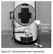
5. Disconnect the ground joint union in the gas piping. Disconnect the remaining pipe from the gas control valve/ thermostat.
6. To remove the gas control valve/thermostat, thread a 4” section of gas pipe into the inlet and use it to turn the FVIR Safety System Operational Checklist TROUBLESHOOTING CHART gas control valve/thermostat (counterclockwise.) Do not use pipe wrench or equivalent to grip body. Damage may result, causing leaks. Do not insert any sharp objects into the inlet or outlet connections. Damage to the gas control valve/ thermostat may result.
Replacing Gas Control Valve/Thermostat
To replace the gas control valve/thermostat, reassemble in reverse order. When replacing the gas control valve/ thermostat, thread a 4” section of gas pipe into the inlet and use it to turn the gas control valve/thermostat (clockwise.) DO NOT OVER TIGHTEN, damage may result.
Be sure to use approved Teflon® tape or pipe joint compound on the gas piping connections and fitting on the back of the gas control valve that screws into tank.
Be sure to remove the pilot ferrule nut from the new gas control valve/thermostat

Turn the gas supply on and check for leaks. Test the water heater by brushing on an approved noncorrosive leak detection solution. Bubbles forming indicate a leak. Correct any leak found.
Be sure tank is completely filled with water before lighting and activating the water heater. Follow the “Lighting Instructions” on page 23.
If additional information is required, contact the Service Department at: 877-552-0010